VY S2 / VZ Calais 8 Way Memory seat into VY S1 Berlina
Note: This method removes all memory functions. Memory wiring is cut so the 8‑way controls operate independently.
1. Remove the seat and side trim. Detach the front‑left rail spring and the black earth wire between the seat base and rail.
2. Unplug all connectors. Disconnect all motor plugs, the 8‑way control module plug, the memory button module plug, and the white seatbelt plug. If the slide motor plug won’t release, leave it connected.
3. Cut memory wiring from the 8‑way control plug. Measure back 10–15 cm from the 8‑way module plug and cut off all wires leading to the memory system.
4. Do the same for the front and rear motor plugs. Cut them free from the memory loom, keeping as much wire length as possible.
5. Cut the backrest motor plug free. Use the white backrest plug (not the yellow/orange airbag plug) and keep maximum wire length.
6. You should now have only the required motor plugs:
- Front motor
- Rear motor
- Backrest motor
- Slide/rail motor (if removable)
7. Set aside the memory loom. It’s no longer needed but can be used later to extend power/earth.
8. Strip out the memory‑related wires. From each motor plug (not the 8‑way control plug), remove only the small wires that originally went to the memory system. Use your loom diagram to confirm.
9. Strip and join the remaining wires. Follow your loom diagram to connect each motor wire correctly. Extend power and earth as needed and fit a new plug or prepare for hardwiring.
10. Tape off the seatbelt loom. The extra white seatbelt plug can simply be taped and heat‑shrunk.
11. Extend wires if required. Usually only power and earth need extra length to avoid tension during seat movement.
12. Route wiring safely. Run all plugs and wires along/under the seat rails, keeping them clear of hinge and rail pinch points.
13. Reconnect the 8‑way control module. Connect power and earth to the vehicle plug and test each motor for correct direction.
14. Refit the seat to the rails. Reconnect the backrest motor plug and earth strap, reinstall the front‑left spring, and test backrest movement.
15. Refit the side trim. Ensure all wiring is taped and clear of moving parts.
16. Reconnect SRS and seatbelt plugs. After leaving the battery disconnected for ~30 minutes, reconnect the airbag and seatbelt plugs and refit all trims.
17. Enjoy your working 8‑way VZ Calais seats in your VY S1 (and VT/VX with 2‑wire power).
If anyone has any troubles don’t hesitate to message me and I can try to help as best as I can.


| Pin | Wire Colour | Function | Motor Plug | Used By | Notes |
|---|---|---|---|---|---|
| 1 | Green/ Blue | Slide Motor | Slide / Track Motor | Slide Motor | |
| 2 | Green/ Red | Front Motor | Front Motor | Front Motor | |
| 3 | Yellow | Rear Motor | Rear Motor | Rear Motor | |
| 4 | Pink | Rear Motor | Rear Motor | Rear Motor | |
| 5 | Black | Front Motor | Front Motor | Front Motor | |
| 6 | Red | Power | — | Car Seat Power Plug | |
| 7 | Maroon | Backrest Motor | Backrest Motor | Backrest Motor | |
| 8 | Brown | Slide Motor | Slide / Track Motor | Slide Motor | |
| 9 | White | Backrest Motor | Backrest Motor | Backrest Motor | |
| 10 | Blue | Earth | — | Car Seat Power Plug | May also be Brown w/ Black trace |
🔌 Car Seat Power Plug
| Wire Colour | Function |
|---|---|
| Orange | Power |
| Blue | Earth |
| Black | — |
Quick viewable / Printable steps
| Preparation | |
|---|---|
| Driver’s door open, doors unlocked, key not in ignition |
| Initial Sequence | Count |
|---|---|
| Insert & remove key from ignition within 5 seconds | x2 |
| Close & open driver’s door within 40 seconds | x2 |
| Insert & remove key from ignition | x1 |
| Close & open driver’s door within 40 seconds | x2 |
| Insert key into ignition and close driver’s door | x1 |
| Programming Mode Entry | |
|---|---|
| Ignition ON then OFF | x1 = Add & Keep Existing |
| Ignition ON then OFF | x2 = Delete & add remotes |
| Remove key | locks cycle |
| Remote Pairing | |
|---|---|
| Press & hold LOCK + UNLOCK on new remote (1.5 seconds) | 2 buttons |
| Press LOCK on remote within 3 seconds | lock button |
| Repeat remote programming steps for each additional remote |
| Exit Programming Mode | |
|---|---|
| Open driver’s door |
had a problem where i was looking for a wiring diagram for a long time now that i have found it and the process
ECU Bosch –
branded ecus marked on the case, they call it
ME7.6.1 – suspect k line comms – untested at this point
ME7.6.2 – CAN comms – tested at this point
Tools to use
Carprog
Abrites
Process & What you can do
- Vin read & Change Vin
- Reset ECU
- Read and Write Immo Data
Things to know that the Carprog goes to do it but it doesn’t complete Tried Different versions still nothing


Ecu Pin Out to obd2 plug
in the image below you dont need all the bullshit get Wider Spades for power 12V
- 12V Power
- 18 & 19
- 49 & 43
- 12v Switch
- 51
Connect can high and can Low use K line as needed and go for it.


At P&G Motors, we specialize in precision diagnostics and manufacturer-authentic repairs. One common issue we see in late-model Mercedes engines—especially the M276—is a camshaft timing error on the left intake bank, often flagged by fault codes like P0016, P0021, or P0018.
⚠️ Symptoms
- Check Engine Light (CEL)
- Rough idle or misfires
- Fault codes for intake camshaft timing (Bank 2)
- Poor fuel economy or sluggish performance
🧭 Bank Orientation – Identifying Left vs. Right Camshaft
On the Mercedes M276 engine, Bank 2 is the left side when viewed from the driver’s seat (i.e., sitting in the car facing forward). So:
- Left camshaft = Bank 2
- Right camshaft = Bank 1
This aligns with the diagnostic references and service procedures for camshaft adjuster faults like P0016 and P0011, which often affect Bank 2 intake timing.
🔍 Root Cause: Tone Wheel Misalignment
The camshaft tone (reluctor) wheel signals camshaft position to the ECU. On the M276, this wheel can rotate independently of the camshaft, causing timing errors even if the chain and adjuster are intact.
At 53° past TDC, the reluctor tooth should be just approaching the magnetic pickup in the camshaft sensor port—not centered, not lagging. If it’s off by ~10°, the wheel has likely slipped.
✅ Inspection Method
- Set crankshaft to 53° past TDC for cylinder 1.
- Remove the intake camshaft sensor on the left bank.
- Look through the sensor port:
- The reluctor tooth should be just about to enter the magnetic pickup zone.
- If it’s already past or lagging behind, the tone wheel is misaligned.
- Check spring load on the camshaft:
- If the cam resists rotation, the wheel is likely still locked.
- If it sits still, the wheel may have rotated independently.
🔧 Repair Options
- Realign the tone wheel using a flathead screwdriver through the sensor port (if accessible).
- Replace the camshaft if the wheel has permanently slipped or damaged its seat.
- Verify timing chain and adjuster integrity before reassembly.
🧠 Why It Matters
Incorrect camshaft timing can cause long-term engine damage, failed emissions tests, and poor drivability. At P&G Motors, we use manufacturer procedures and precision tools to ensure your Mercedes runs exactly as intended.
📞 Book Your Diagnostic Today
If your Mercedes is showing timing errors or running rough, contact us for a full inspection. We’ll confirm tone wheel alignment, sensor signal integrity, and timing chain condition—no guesswork, no generic fixes.
Starter relay
there is nothing in the workshop manual to tell you where apart from the start cut relay,.
you go test it and it works,
you pull up the scan data and every thing on the live data works but still no out put to the starter motor solenoid red wire,
so then you look look look read the workshop manual and find this

THEN YOU GET TO THIS PART

NOW THERE IS NO BOLD HEADING OR ANYTHING LIKE THAT
SO THEN I JUST STARTED TO PULL THE CAR APAPRT AND FOUND ANOTHER FUSE BOX UNDER THE LEFT FRONT HEAD LIGHT
SMASHED COVER FROM A ACCIDENT AND THE REALY IS FULL OF WATER
FUCK YOU HONDA
The fault code P0AA6 – hybrid battery isolation fault is what the name suggests the wiring between units is not good, but there are sub codes and how to quickly identify what to do
SUB CODES / INF Codes
526 – vehicles orange cables are shorting somewhere water in harness plug ( corrosion ) clean harness plugs and check resistance should be in the 3 M,Ohms and higher region so the book says i usually see 30m ohms or higher or nothing at all ( ultimately )
611 – AC Compressor is shorting out ( most common )
612 – Battery is shorting out to the frame
613 – Electric Motors Shorting
614 – Invertor is shorting
Where to Find the Subcodes ?
Quick Answer is Tech Stream in the freeze frames for the Fault
Some show in the live data ( Year model Pending ).
Search for the PID ( Detail Codes 1 though 5 ) this will show you the results of the tests carried out every time you start the car, or delete the fault code it will run the tests again.
* quick hint * if you turn on the a/c and its the compressor is shorted. the check battery sign will come up on cluster quicker. and if fuse blown in inverter you will get the B1498 Fault listed below.

B1498 – Communication Malfunction (A-C invertor local)
what they don’t tell you is that it could be the fuse in the Inverter Take the cap off and look at the fuse white crystals it should still have ohm resistance to work
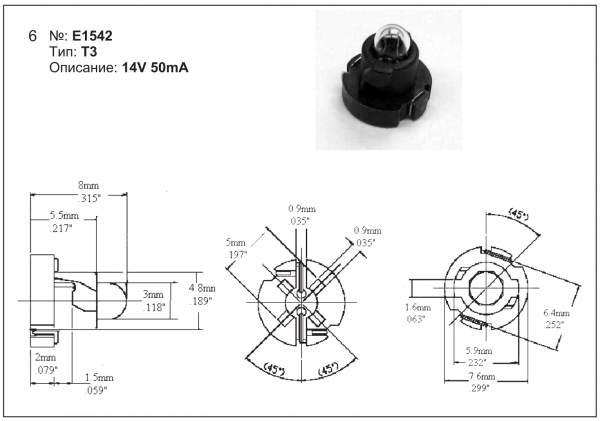
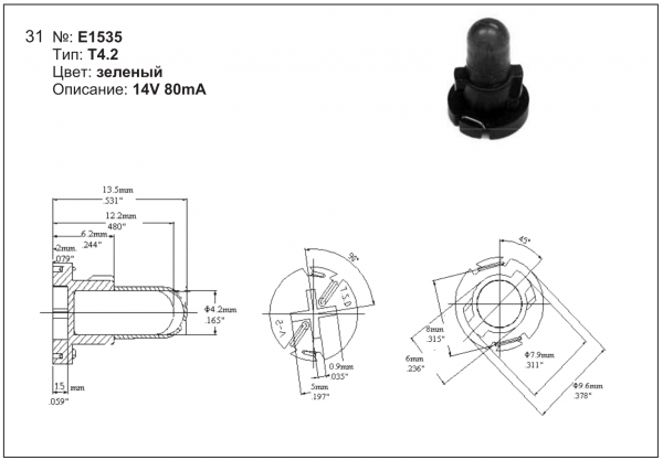
The dash globes are as follows
T3
not too sure where it fits
T4
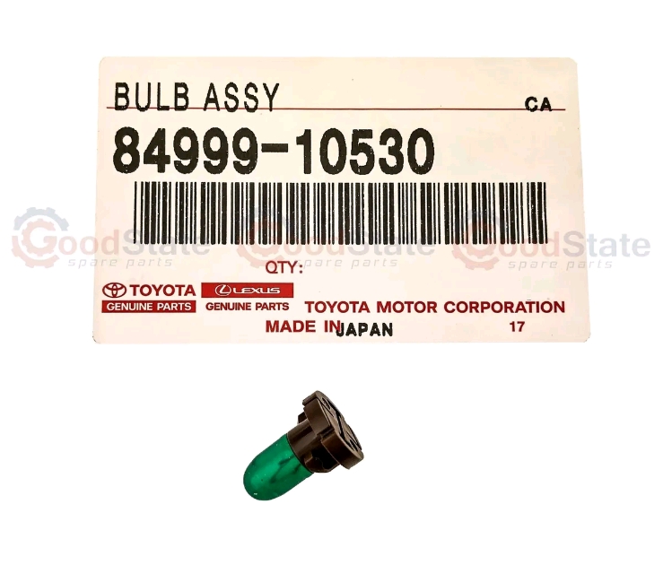
T4.2 –
Flush mount globe usually fitted to hard circuit board, always the globe you don’t have as the globe is not replaceable easily with out the plastic base.
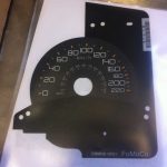
fitted to Toyota’s clocks Ford falcon clocks and instrument clusters as a back light
T5. Normally replaceable
DIAGNOSTIC CHARTS – V6 Engines,
ABS DIAGNOSTIC TROUBLE CODE TABLE
DTC CODE DESCRIPTION
12 No Fault
21 Front Right Wheel Speed Sensor Incorrect Signal
23 Front Right Wheel Speed Sensor Short Circuit or Open Circuit
25 Front Left Wheel Speed Sensor Incorrect Signal
27 Front Left Wheel Speed Sensor Short Circuit or Open Circuit
28 Wheel Speed Sensor Frequency Error
31 Rear Right Wheel Speed Sensor Incorrect Signal
33 Rear Right Wheel Speed Sensor Short Circuit or Open Circuit
35 Rear Left Wheel Speed Sensor Incorrect Signal
37 Rear Left Wheel Speed Sensor Short Circuit or Open Circuit
41 Front Right Inlet Valve Solenoid Fault
42 Front Right Outlet Valve Solenoid Fault
45 Front Left Inlet Valve Solenoid Fault
46 Front Left Outlet Valve Solenoid Fault
55 Rear Axle Inlet Valve Solenoid Fault
56 Rear Axle Outlet Valve Solenoid Fault
61 Pump Motor or Relay Fault
63 Valve Solenoid Relay Circuit Fault
67 Stop Lamp Switch Circuit Fault
71 Control Module Internal Fault
85 System Voltage Too Low
DIAGNOSTIC CHARTS – GEN III V8 Engine, V8 – WITH THROTTLE RELAXER
ABS/TCS DIAGNOSTIC TROUBLE CODE TABLE
DTC CODE DESCRIPTION
12 No Fault
21 Front Right Wheel Speed Sensor Incorrect Signal
23 Front Right Wheel Speed Sensor Short Circuit or Open Circuit
25 Front Left Wheel Speed Sensor Incorrect Signal
27 Front Left Wheel Speed Sensor Short Circuit or Open Circuit
28 Wheel Speed Sensor Frequency Error
31 Rear Right Wheel Speed Sensor Incorrect Signal
33 Rear Right Wheel Speed Sensor Short Circuit or Open Circuit
35 Rear Left Wheel Speed Sensor Incorrect Signal
37 Rear Left Wheel Speed Sensor Short Circuit or Open Circuit
41 Front Right Inlet Valve Solenoid Fault
42 Front Right Outlet Valve Solenoid Fault
45 Front Left Inlet Valve Solenoid Fault
46 Front Left Outlet Valve Solenoid Fault
47 Priming Valve Solenoid Fault
48 Switching Valve Solenoid Fault
51 Rear Right Inlet Valve Solenoid Fault
52 Rear Right Outlet Valve Solenoid Fault
55 Rear Left Inlet Valve Solenoid Fault
56 Rear Left Outlet Valve Solenoid Fault
58 Throttle Relaxer PWM (Pulse Width Modulation) Interface Fault
61 Pump Motor or Relay Fault
62 RPM Signal Fault (refer diagnostic charts in both the V6 and GEN III V8 Sections
63 Valve Solenoid Relay Circuit Fault
64 Throttle Relaxer Control Module Position Fault
65 Throttle Relaxer Motor Fault
66 Throttle Relaxer Control Fault
67 Stop Lamp Switch Circuit Fault
68 TPS (Throttle Position Sensor) Monitoring Fault
71 Control Module Internal Fault
72 Serial Data Fault (refer diagnostic charts in both the V6 and GEN III V8 Sections)
73 Spark Retard Monitoring Fault (refer diagnostic charts in both the V6 and GEN III V8 Sections)
73 Requested Torque Circuit Fault – V6 Engines Only
74 Actual Torque Circuit Fault – V6 Engines Only
78 Incorrect Option Coding
85 System Voltage Too Low

Products
-
 Holden ECU Programing - VIN Changing - Tuner Unlocking
$150.00
Holden ECU Programing - VIN Changing - Tuner Unlocking
$150.00
-
 Battery's From $135
-
 P & G Work Shirt Pit crew Style
$25.00
P & G Work Shirt Pit crew Style
$25.00
-
 F150 Raptor KMH Speedo overlay
$115.00
F150 Raptor KMH Speedo overlay
$115.00
-
 MAZDA ROTARY BOSCH ALTERNATOR HIGH OUTPUT 110 AMP
Original price was: $455.00.$400.00Current price is: $400.00.
MAZDA ROTARY BOSCH ALTERNATOR HIGH OUTPUT 110 AMP
Original price was: $455.00.$400.00Current price is: $400.00.