# Holden Commodore VE Series 1 – 6.0L V8 – E38 Ecu’s , Pedal’s, Throttle body’s. DTC P2138: Accelerator Pedal Position Sensor 1-2 Correlation
05/03/2022 | Author: admin | No comments | Categories: Diagnostics • Ecu swap and reading • Holden • News & Blog • Recent News and Posts • Repairs
# Holden Commodore VE Series 1, 2006-2010 – 6.0L V8 – Throttle body and ECU part number notes before you start
3) E38: Keep to flashing files from these year groups to the service numbers listed: wire harness Same on a) b) c)
a) 2006 – 2007 – E38 – VZ & VE Holden Commodores with the L76 and L98 V8 OS12612381 & 12624402 – Hardware/Service # (12597 121) – Silver Throttle Body other service numbers 12597121, 12603892, 12589297, 19210738 that can be used to replace the 121
b) OS????????? – 2008.5 – 2009 – E38 – VE Holden Commodores with the L76 L98 6.0L V8 OS???????? – Hardware/Service # (12612 384) – Gold Throttle body other service numbers???
c) 2009 – 2010 – E38 – VE Holden Commodores with the L76 L98 6.0L V8 OS???????? – Hardware/Service # (12625 455) – Gold Throttle body other service numbers??? Wiring harness different from here down
d) OS????????? – 2010+ E38 (service number ending in 238) and into VF Commodore
### Hp Tuners – Doesnt always work,
The P2138 Fault code every one has and no one can solve it – Most tuners send it to an auto electrician which ends up a dead end
### Every thing i have tried So far
⇒ Cutting the APP S1 and S2 and joining With resistor to half the output voltage< ⇒ Installing Different ECU and Programming ⇒ Installing Multiple Pedals, ⇒ Installing New Harness’ To Pedal and to Throttle body ( including new PCM Pins and Plugs) ⇒ Ignition is only Needed to be turned on Moving pedal slowly is ok But move it too fast and it Doesnt like it Sets the P2138 ⇒ Install later PCM Type ‘455’ with gold blade and try with that combo Still The Same only it does at 40% APP (Different Setup in Gold Blade
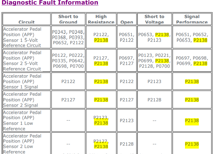
# DTC P2138: Accelerator Pedal Position Sensor 1-2 Correlation
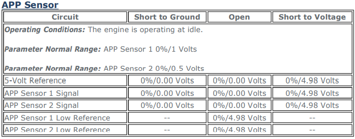
Typical Scan Tool Data
### APP – Circuit/System Description
The accelerator pedal assembly contains two accelerator pedal position (APP) sensors. The APP sensors are mounted in the pedal assembly and are not serviceable. The APP sensors provide a signal voltage that changes relative to the position of the accelerator pedal. The engine control module (ECM) supplies a separate 5-volt reference and low reference circuit for each of the APP sensors.
The APP sensor 1 signal voltage increases as the pedal is depressed, from approximately 1.0 volt at rest to approximately 4 volts when fully depressed. The APP sensor 2 signal voltage increases as the pedal is depressed, from approximately 0.5 volt at rest to approximately 2 volts with the accelerator pedal fully depressed.
### Conditions for Running the DTCs
- The ignition is ON or the engine is operating.
- The ignition voltage is greater than 7 volts.
- The DTCs run continuously once the above conditions are met.
- The ECM detects that the voltage difference between APP sensor 1 and the calculated idle
- The ECM detects that the voltage difference between APP sensor 2 and the calculated idle
- The ECM detects that the voltage difference between APP sensor 1 and 2 is greater than
- The ECM detects that the voltage difference between APP sensor 1 and 2 is greater than
- The ECM detects that the voltage difference between APP sensor 1 and 2 is greater than
- Any of the above conditions exist for greater than 1 second, or a cumulative of 10 seconds.
- Ignition ON, observe the DTC information with a scan tool. DTC P0651, P0652, P0653,
- Observe the scan tool APP Sensor voltage parameters. Verify both of the APP sensor voltages
- Rapidly depress the accelerator pedal from the rest position to the wide open throttle position
- Slowly depress the accelerator pedal to WOT and then slowly return the pedal to closed
- Operate the vehicle within the Conditions for Running the DTC to verify the DTC does not
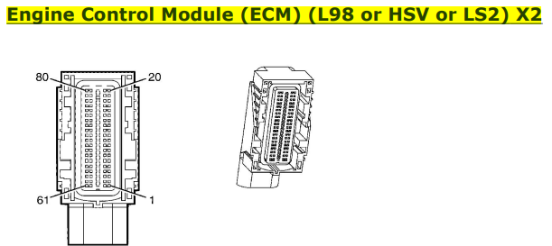
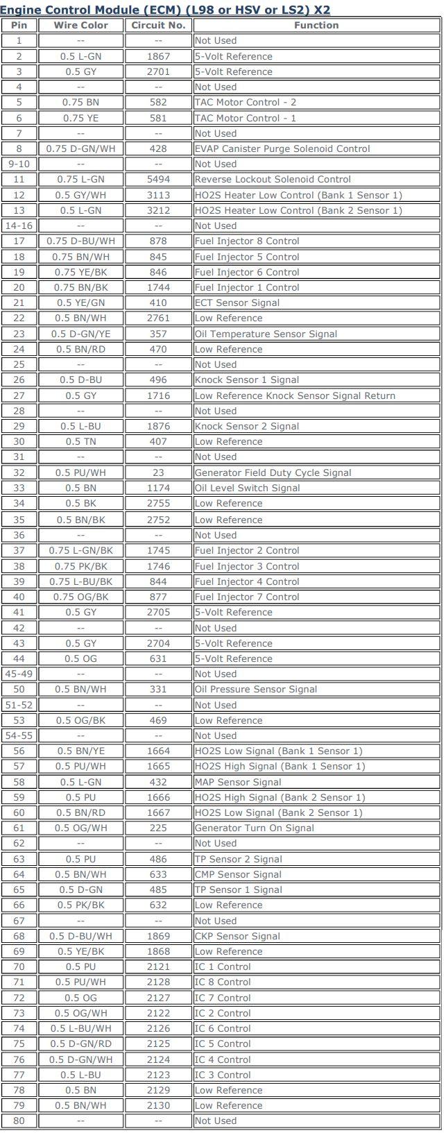
- Ignition OFF, remove the fuse that supplies B+ to terminal 56 X2 of the ECM.
- Disconnect the harness connector at the accelerator pedal assembly.
- Test for less than 5 Ω between the appropriate low reference circuit listed below and ground.
- Install the fuse that supplies B+ to terminal 56 X2 of the ECM.
- Ignition ON, test for 4.8-5.2 V between the appropriate 5-volt reference circuit listed below
- Circuit Testing
- Connector Repairs
- Testing for Intermittent Conditions and Poor Connections
- Wiring Repairs
- APP sensor 1 terminal 4
- APP sensor 2 terminal 5
- APP sensor 1 terminal 2
- APP sensor 2 terminal 1
- Observe the scan tool APP sensor 1 voltage parameter. Verify the voltage is less than 0.3 V.
- Observe the scan tool APP sensor 2 voltage parameter. Verify the voltage is less than 0.3 V.
- Connect a 3 A fused jumper wire between the APP sensor 1 signal circuit terminal 3 and the 5-volt reference circuit terminal 2. Verify the APP sensor 1 voltage parameter is greater than 4.8 V.
- Connect a 3 A fused jumper wire between the APP sensor 2 signal circuit terminal 6 and the 5-volt reference circuit terminal 1. Verify the APP sensor 2 voltage parameter is greater than 4.8 V.
- If all circuits/connections test normal, test or replace the accelerator pedal assembly.
# After Reading all this the FIX, you want to know the FIX???
SIMPLES
⇒ Connect all powers and grounds for app1 and app2 together, ⇒ ADD in two 110 ohm resistors in series from app1 (0v to5v app) to the App2 line (0v to 2.5v) What it does is Makes both the App1 and App2 be similar all the time. With out the ecu knowing that there is a high or low loss anywhere. BINGO ( Im in Miami Bitch ) All the rest of the shit above you need to know but its irrelivant.//
18-03-2022 – UPDATE – This Slows it down It Still Happens When you move Too Fast on the pedal
Found another reason – Add Ground to PCM Case.
Found Another reason – Try Disconnecting Fans. (temporarily)
### Related
Book in
Similar issue on your vehicle? Call the workshop and we will advise what to expect.