# Toyota Hiace GDH300 Series – Front Radar sensor Calibration
03/04/2020 | Author: admin | No comments | Categories: ADAS Calibrations • Diagnostics • Toyota
# Front Radar sensor Calibration – Preparation phase
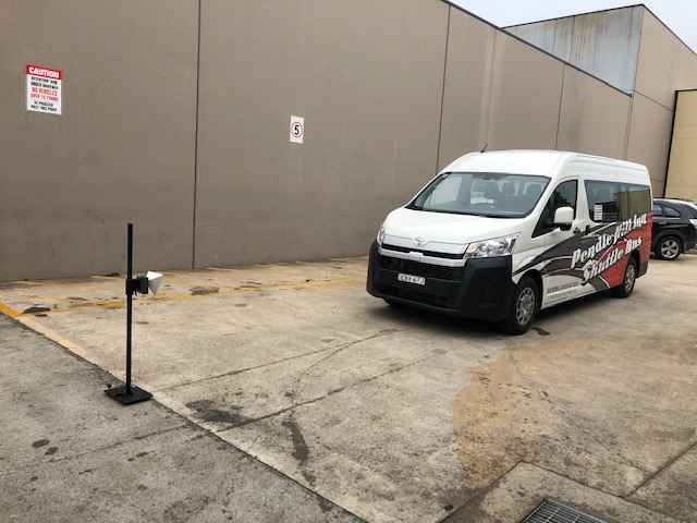
The Vehicle had came in from a panel shop with the front radar module replaced so typically the unit had to be recalibrated, (this also needs to be done if the grille has been removed and replaced, modified etc)
The vehicle was scanned and faults relating to other systems where found but none for the front radar system (which was strange) fault code for PCS – Pre collision system, had a fault, U023587 – lost communications with cruise control front distance range sensor single sensor or center missing message.
This started the pathway for the calibration of the front radar sensor, this was completed and no error messages on the instrument cluster was found.
We had used the Autel Maxisys to calibrate the sensor through the ADAS Calibration pages, and then went for a drive the active cruise control came on but it did not slow the vehicle down when coming up to a vehicle doing cruise control we had thought the system had active braking hence active cruise control, this did not work (image handing the vehicle back to the client to find out the system did not work and you had not tested it correctly) hmmmm.
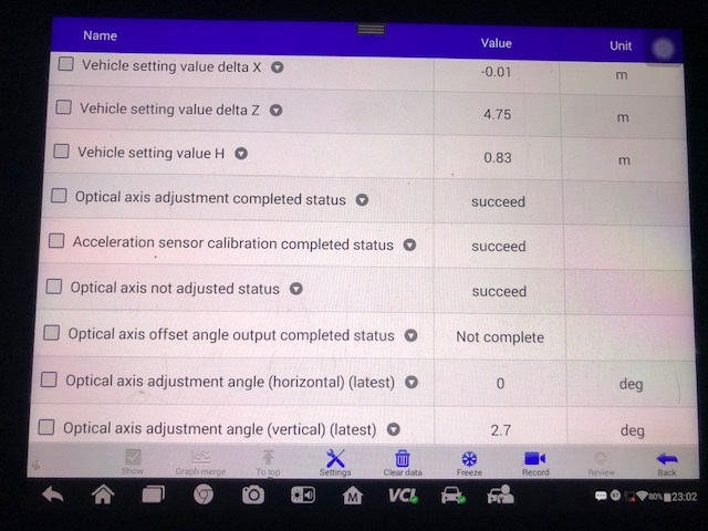
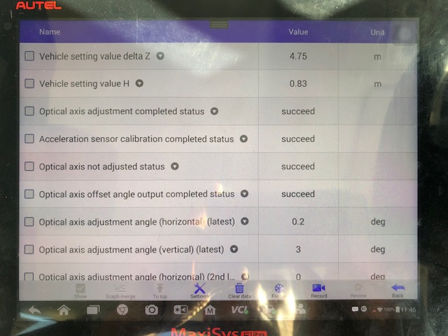
We had found the live data PIDS and found optical axis offset angle output completed status was not complete, this is when we consulted the the genuine methods of how to set it up correctly (There is a lot of new terminology to Learn, and requires peace and quiet when learning a new system)
This is an issue, this had to be where we needed to start to finish the job. the live data PID and the Second Step did not read the same English words which is what had us mislead in the first place.
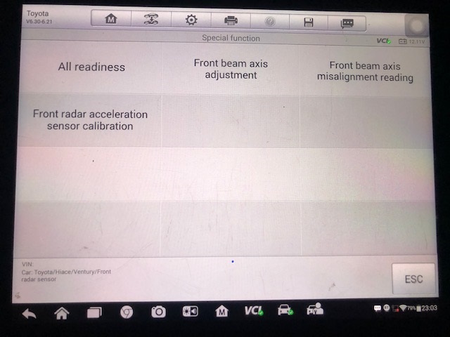
We had looked up how to carry out the system and used the right tools to do the work, we found the genuine procedure online and investigated further and found that you have to go into the front radar system and complete the ADAS calibration steps, listed below,
- Front Beam Axis Adjustment,
- Front Beam Axis Misalignment reading
- Front Radar Acceleration Sensor Calibration
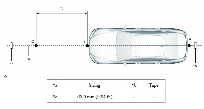
# Procedures as listed by Toyota
Mark point C (SST (reflector) placement position) at a position 3000 mm (9.84 ft.) from point B. Place SST (reflector) at point C. (as above image)
Front Beam Axis Adjustment:
Note:
- Close all of the doors.
- Ensure that nobody enters the adjustment area during the adjustment.
- Do not move or shake the vehicle during adjustment (do not get in or out of the vehicle).
- During the procedure, do not enter the adjustment area.
- Do not turn off the GTS or power switch.
- Close all of the doors.
- Ensure that nobody enters the adjustment area during the adjustment.
- Do not move or shake the vehicle during adjustment (do not get in or out of the vehicle).
- During the procedure, do not enter the adjustment area.
- Do not turn off the GTS or power switch.
- Enter the following menus: Body Electrical / Pre-Collision 2 / Utility.- Body Electrical > Pre-Collision 2 > UtilityTester DisplayFront Beam Axis Offset Reading
- According to the display on the GTS, press “Next”.
- Perform the adjustment according to the display on the GTS.Specified ConditionVertical learning value0 degHorizontal learning value0 degNote:If the result is not as specified, perform beam axis adjustment again.
# After carrying out and still not working with adaptive cruise control
the vehicle had suceeded in all the PID data now but adaptive cruise still not working,
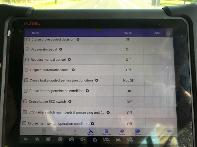
below is the data line from the front radar sensor and radar cruise 1 module.
we had the system calibrated, for succeed messages every where but found another PID line that made it not ready
This is in the front radar live data PIDS
The front radar was adjusted and calibrated again to check the difference,
AND WE REALISED THAT THE VEHICLE WAS NOT EQUIPPED WITH ACTIVE CRUISE CONTROL SO THE FEATURE WOULD NEVER WORK AT LEAST WE UNDERSTAND IT NOW
# To the Future and we are ready
It does look like this procedure will become quite common practice on newer model Toyota’s we look forward to helping you next time you have moved the Front Radar Module
Book in
Similar issue on your vehicle? Call the workshop and we will advise what to expect.