🔁 Reset Procedures (Start Here)
Reset A – Basic
- Ignition ON
- Open window halfway
- Fully close using UP switch
- Hold UP for 1 second
- Test AUTO DOWN
Reset B – Auto-Reverse Fault
- AUTO UP 10 times (window closes then opens slightly)
- Confirm AUTO UP stops responding
- Perform Reset A
- Retest AUTO UP/DOWN
If reset fails, proceed to connector-level diagnostics below.
⚠️ Key Notes Before Testing
- All switches are CPU-controlled — never probe with a standard test light
- Pulse durations:
- AUTO UP ≈ 130 ms
- AUTO DOWN ≈ 300 ms
- Manual hold = steady voltage while pressed
- Ground faults can suppress pulses — verify ground integrity before chasing signal loss
- Use a powered oscilloscope across motor terminals or switch outputs
🧠 Ground Fault Suppression – How It Stops Pulses
In this CPU‑controlled system, the motor ground pin is part of the control reference. If the CPU detects an abnormal ground condition, it will inhibit or instantly cut the UP/DOWN output.
Fault Modes
| Fault Type | Electrical Effect | CPU Reaction | Scope Result |
|---|---|---|---|
| High‑resistance / open ground | Ground floats above 0 V under load | CPU inhibits output entirely | Flat trace (no pulse) |
| Hard short to ground | Output driver sees permanent low | CPU detects overcurrent and shuts down | Very brief blip or none at all |
Scope Examples
Normal AUTO UP (~130 ms pulse) ⬜────────▮▮▮▮▮────────
Normal AUTO DOWN (~300 ms pulse) ⬜────────█████████────────
Suppressed by open/high‑resistance ground ⬜──────────────────────── (flat line)
Suppressed by hard short to ground ⬜─▏────────────────────── (tiny blip, then flat)
Tip: Always scope at D3 first. If no pulse, check ground continuity and load‑test it before suspecting the master switch.
🔧 Master Switch (RHD Driver’s Side)


🧠 Diagnostic Implications
- Each window has dedicated UP/DOWN lines from the master switch to D3 — no shared “Pin 14” logic line in this model
- Rear windows have a common/control feed (G/B) per side, but not shared between sides
- If a single UP/DOWN line is shorted or grounded, only that window fails
- If the master switch CPU detects a fault, it may disable all outputs (full system lockout)
- Ground faults on motor ground pins can suppress pulses entirely
🔍 Oscilloscope Setup Tips
- Trigger: rising edge, ~8–10 V
- Timebase: 200 ms/div for AUTO pulses
- For manual hold: widen timebase and look for steady high while pressed
- Always back-probe at D3 first — isolates door harness from body harness faults
🧩 Fault Logic Summary
- Rear window fault (e.g., grounded Pin 14) can suppress all window functions
- Master switch CPU may enter protection mode
- No pulses visible on oscilloscope if logic is suppressed
- Front motors are independently wired—failures are isolated unless CPU halts

Products
-
 Holden ECU Programing - VIN Changing - Tuner Unlocking
$150.00
Holden ECU Programing - VIN Changing - Tuner Unlocking
$150.00
-
 Battery's From $135
-
 P & G Work Shirt Pit crew Style
$25.00
P & G Work Shirt Pit crew Style
$25.00
-
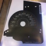 F150 Raptor KMH Speedo overlay
$115.00
F150 Raptor KMH Speedo overlay
$115.00
-
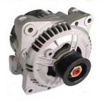 MAZDA ROTARY BOSCH ALTERNATOR HIGH OUTPUT 110 AMP
Original price was: $455.00.$400.00Current price is: $400.00.
MAZDA ROTARY BOSCH ALTERNATOR HIGH OUTPUT 110 AMP
Original price was: $455.00.$400.00Current price is: $400.00.