VY S2 / VZ Calais 8 Way Memory seat into VY S1 Berlina
Note: This method removes all memory functions. Memory wiring is cut so the 8‑way controls operate independently.
1. Remove the seat and side trim. Detach the front‑left rail spring and the black earth wire between the seat base and rail.
2. Unplug all connectors. Disconnect all motor plugs, the 8‑way control module plug, the memory button module plug, and the white seatbelt plug. If the slide motor plug won’t release, leave it connected.
3. Cut memory wiring from the 8‑way control plug. Measure back 10–15 cm from the 8‑way module plug and cut off all wires leading to the memory system.
4. Do the same for the front and rear motor plugs. Cut them free from the memory loom, keeping as much wire length as possible.
5. Cut the backrest motor plug free. Use the white backrest plug (not the yellow/orange airbag plug) and keep maximum wire length.
6. You should now have only the required motor plugs:
- Front motor
- Rear motor
- Backrest motor
- Slide/rail motor (if removable)
7. Set aside the memory loom. It’s no longer needed but can be used later to extend power/earth.
8. Strip out the memory‑related wires. From each motor plug (not the 8‑way control plug), remove only the small wires that originally went to the memory system. Use your loom diagram to confirm.
9. Strip and join the remaining wires. Follow your loom diagram to connect each motor wire correctly. Extend power and earth as needed and fit a new plug or prepare for hardwiring.
10. Tape off the seatbelt loom. The extra white seatbelt plug can simply be taped and heat‑shrunk.
11. Extend wires if required. Usually only power and earth need extra length to avoid tension during seat movement.
12. Route wiring safely. Run all plugs and wires along/under the seat rails, keeping them clear of hinge and rail pinch points.
13. Reconnect the 8‑way control module. Connect power and earth to the vehicle plug and test each motor for correct direction.
14. Refit the seat to the rails. Reconnect the backrest motor plug and earth strap, reinstall the front‑left spring, and test backrest movement.
15. Refit the side trim. Ensure all wiring is taped and clear of moving parts.
16. Reconnect SRS and seatbelt plugs. After leaving the battery disconnected for ~30 minutes, reconnect the airbag and seatbelt plugs and refit all trims.
17. Enjoy your working 8‑way VZ Calais seats in your VY S1 (and VT/VX with 2‑wire power).
If anyone has any troubles don’t hesitate to message me and I can try to help as best as I can.


| Pin | Wire Colour | Function | Motor Plug | Used By | Notes |
|---|---|---|---|---|---|
| 1 | Green/ Blue | Slide Motor | Slide / Track Motor | Slide Motor | |
| 2 | Green/ Red | Front Motor | Front Motor | Front Motor | |
| 3 | Yellow | Rear Motor | Rear Motor | Rear Motor | |
| 4 | Pink | Rear Motor | Rear Motor | Rear Motor | |
| 5 | Black | Front Motor | Front Motor | Front Motor | |
| 6 | Red | Power | — | Car Seat Power Plug | |
| 7 | Maroon | Backrest Motor | Backrest Motor | Backrest Motor | |
| 8 | Brown | Slide Motor | Slide / Track Motor | Slide Motor | |
| 9 | White | Backrest Motor | Backrest Motor | Backrest Motor | |
| 10 | Blue | Earth | — | Car Seat Power Plug | May also be Brown w/ Black trace |
🔌 Car Seat Power Plug
| Wire Colour | Function |
|---|---|
| Orange | Power |
| Blue | Earth |
| Black | — |
VY S2 / VZ Calais 8 Way Memory seat into VY S1 Berlina
So with the help of one very friendly and helpful person I have worked out how to install VZ Calais 8 Way Memory seats into a S1 VY Berlina without the memory and I figured I would do a write up in the hopes that it can help others.
Please note: This method removes all of the memory functions as wires need to be cut and removed in order for the 8 way controls to work alone.
Step 1. Remove your seat and seat side trim from the seat base / rail. You will need to remove the spring at the front left of the rail and then remove the earth wire which is a single black wire going from the seat base to the rail.
Step 2. Unplug all the connections / plugs from the motors and the 8 way control module, Memory Button Control Module plug and also the extra white seatbelt plug, you may find that the slide / rail motor plug is hard to remove, no problem just leave it plugged in.
Step 3. Grab the plug and wires which plugs into the 8 way control module, come back from the plug about 10-15 cm and cut off all the wires from the memory plugs.
Step 4. Grab the plugs that go into the front and rear Motor and do the same thing but get as much length as you can cutting it off the memory plugs.
Step 5. Grab the white plug that goes into the back rest (NOT THE YELLOW / ORANGE AIRBAG PLUG), should be a white plug, do the same allowing yourself as much length as possible.
Step 6. You should now be left with only the plugs pictured below in Photo “Plugs” which are 1x Front Motor Plug, 1x Rear Motor Plug, 1x Backrest Motor Plug and if you could get it off, 1x Slide / Rail motor plug otherwise it will be there just not removed.
Step 7. You can now put all the memory function wiring aside as none of it is needed for the 8 way controls and motors to work alone but dont throw it out as it can be used to extend the Power and Earth later on.
Step 8. Grab just the plugs that power the motors (NOT THE 8 WAY CONTROL PLUG YOU NEED ALL THEM WIRES INTACT) so 1x Front Motor Plug, 1x Rear Motor Plug, 1x Backrest Motor Plug and 1x Slide / Rail Plug and remove ONLY THE SMALL WIRES that connect to the memory plugs, if you are unsure of which wires to remove refer to the Loom and look at the X’s on each plug.
Step 9. Now strip back all the ends of the remaining wires as they all need to be connected to one another using the Loom diagram that I have made below. Remember to extend the Power and Earth and either put a new Plug on the end or hardwire it in later when you are ready to test it all. (I hope the diagram makes sense, I figured if any of the wire colours are different that the locations of each pin and function will remain the same so follow the numbers if that is the case.)
Step 10. You may notice that there is an extra loom and plug that comes from the seatbelt which should be a white plug, I would not worry about cutting this, I just simply taped up and heat shinked the end of the plug.
Step 11. This step is only required if your wires are to short. You may have to extend some of the wires if they are to short, the only wires I had to extend were my Power and Earth as they did not reach right back and I wanted peace of mind that they had enough slack to not be pulled tight when the seat is in motion.
Step 12. You can now Run the wires / plugs through and under / alongside the seat rail to their required motors making sure they are taped up and out of any pinch zones of the seat hinges / rails.
Step 13. Now is the time to plug back in the 8 Way Control Plug back into the 8 Way Control Module and then plug the Power and Earth from the 8 Way Control Plug into the Car Plug Power and Earth, test that each motor is going in the correct direction corresponding to which control is activated, if all good proceed to next step.
Step 14. You can now put the seat back onto the Seat rail / base remembering to plug in the Backrest motor plug and the Earth from the Seat back into its place on the rail / base then do the same for the spring at the front left side of the rail, you can now test the backrest motor and if it reclines back and forth then you are all good to go.
Step 15. Place the seat side trim back on and screw it back once again making sure all the wiring is taped up and out of the way of any pinch points in the rails hinges.
Step 16. Leave your battery disconnected for 30 minutes or so then recconect the the SRS Airbag plug and Seatbelt Plug then replace all the surrounding seat trims making sure again that no wiring will get caught / snagged on the trims when the seat is in motion.
Step 17: Sit and Enjoy your 8 Way VZ Calais seats in your VY S1 and maybe even VT VX aslong as it has a 2 Wire Car Plug.
If anyone has any troubles don’t hesitate to message me and I can try to help as best as I can.
Quick viewable / Printable steps
| Preparation | |
|---|---|
| Driver’s door open, doors unlocked, key not in ignition |
| Initial Sequence | Count |
|---|---|
| Insert & remove key from ignition within 5 seconds | x2 |
| Close & open driver’s door within 40 seconds | x2 |
| Insert & remove key from ignition | x1 |
| Close & open driver’s door within 40 seconds | x2 |
| Insert key into ignition and close driver’s door | x1 |
| Programming Mode Entry | |
|---|---|
| Ignition ON then OFF | x1 = Add & Keep Existing |
| Ignition ON then OFF | x2 = Delete & add remotes |
| Remove key | locks cycle |
| Remote Pairing | |
|---|---|
| Press & hold LOCK + UNLOCK on new remote (1.5 seconds) | 2 buttons |
| Press LOCK on remote within 3 seconds | lock button |
| Repeat remote programming steps for each additional remote |
| Exit Programming Mode | |
|---|---|
| Open driver’s door |
had a problem where i was looking for a wiring diagram for a long time now that i have found it and the process
ECU Bosch –
branded ecus marked on the case, they call it
ME7.6.1 – suspect k line comms – untested at this point
ME7.6.2 – CAN comms – tested at this point
Tools to use
Carprog
Abrites
Process & What you can do
- Vin read & Change Vin
- Reset ECU
- Read and Write Immo Data
Things to know that the Carprog goes to do it but it doesn’t complete Tried Different versions still nothing


Ecu Pin Out to obd2 plug
in the image below you dont need all the bullshit get Wider Spades for power 12V
- 12V Power
- 18 & 19
- 49 & 43
- 12v Switch
- 51
Connect can high and can Low use K line as needed and go for it.

🔁 Reset Procedures (Start Here)
Reset A – Basic
- Ignition ON
- Open window halfway
- Fully close using UP switch
- Hold UP for 1 second
- Test AUTO DOWN
Reset B – Auto-Reverse Fault
- AUTO UP 10 times (window closes then opens slightly)
- Confirm AUTO UP stops responding
- Perform Reset A
- Retest AUTO UP/DOWN
If reset fails, proceed to connector-level diagnostics below.
⚠️ Key Notes Before Testing
- All switches are CPU-controlled — never probe with a standard test light
- Pulse durations:
- AUTO UP ≈ 130 ms
- AUTO DOWN ≈ 300 ms
- Manual hold = steady voltage while pressed
- Ground faults can suppress pulses — verify ground integrity before chasing signal loss
- Use a powered oscilloscope across motor terminals or switch outputs
🧠 Ground Fault Suppression – How It Stops Pulses
In this CPU‑controlled system, the motor ground pin is part of the control reference. If the CPU detects an abnormal ground condition, it will inhibit or instantly cut the UP/DOWN output.
Fault Modes
| Fault Type | Electrical Effect | CPU Reaction | Scope Result |
|---|---|---|---|
| High‑resistance / open ground | Ground floats above 0 V under load | CPU inhibits output entirely | Flat trace (no pulse) |
| Hard short to ground | Output driver sees permanent low | CPU detects overcurrent and shuts down | Very brief blip or none at all |
Scope Examples
Normal AUTO UP (~130 ms pulse) ⬜────────▮▮▮▮▮────────
Normal AUTO DOWN (~300 ms pulse) ⬜────────█████████────────
Suppressed by open/high‑resistance ground ⬜──────────────────────── (flat line)
Suppressed by hard short to ground ⬜─▏────────────────────── (tiny blip, then flat)
Tip: Always scope at D3 first. If no pulse, check ground continuity and load‑test it before suspecting the master switch.
🔧 Master Switch (RHD Driver’s Side)


🧠 Diagnostic Implications
- Each window has dedicated UP/DOWN lines from the master switch to D3 — no shared “Pin 14” logic line in this model
- Rear windows have a common/control feed (G/B) per side, but not shared between sides
- If a single UP/DOWN line is shorted or grounded, only that window fails
- If the master switch CPU detects a fault, it may disable all outputs (full system lockout)
- Ground faults on motor ground pins can suppress pulses entirely
🔍 Oscilloscope Setup Tips
- Trigger: rising edge, ~8–10 V
- Timebase: 200 ms/div for AUTO pulses
- For manual hold: widen timebase and look for steady high while pressed
- Always back-probe at D3 first — isolates door harness from body harness faults
🧩 Fault Logic Summary
- Rear window fault (e.g., grounded Pin 14) can suppress all window functions
- Master switch CPU may enter protection mode
- No pulses visible on oscilloscope if logic is suppressed
- Front motors are independently wired—failures are isolated unless CPU halts


At P&G Motors, we specialize in precision diagnostics and manufacturer-authentic repairs. One common issue we see in late-model Mercedes engines—especially the M276—is a camshaft timing error on the left intake bank, often flagged by fault codes like P0016, P0021, or P0018.
⚠️ Symptoms
- Check Engine Light (CEL)
- Rough idle or misfires
- Fault codes for intake camshaft timing (Bank 2)
- Poor fuel economy or sluggish performance
🧭 Bank Orientation – Identifying Left vs. Right Camshaft
On the Mercedes M276 engine, Bank 2 is the left side when viewed from the driver’s seat (i.e., sitting in the car facing forward). So:
- Left camshaft = Bank 2
- Right camshaft = Bank 1
This aligns with the diagnostic references and service procedures for camshaft adjuster faults like P0016 and P0011, which often affect Bank 2 intake timing.
🔍 Root Cause: Tone Wheel Misalignment
The camshaft tone (reluctor) wheel signals camshaft position to the ECU. On the M276, this wheel can rotate independently of the camshaft, causing timing errors even if the chain and adjuster are intact.
At 53° past TDC, the reluctor tooth should be just approaching the magnetic pickup in the camshaft sensor port—not centered, not lagging. If it’s off by ~10°, the wheel has likely slipped.
✅ Inspection Method
- Set crankshaft to 53° past TDC for cylinder 1.
- Remove the intake camshaft sensor on the left bank.
- Look through the sensor port:
- The reluctor tooth should be just about to enter the magnetic pickup zone.
- If it’s already past or lagging behind, the tone wheel is misaligned.
- Check spring load on the camshaft:
- If the cam resists rotation, the wheel is likely still locked.
- If it sits still, the wheel may have rotated independently.
🔧 Repair Options
- Realign the tone wheel using a flathead screwdriver through the sensor port (if accessible).
- Replace the camshaft if the wheel has permanently slipped or damaged its seat.
- Verify timing chain and adjuster integrity before reassembly.
🧠 Why It Matters
Incorrect camshaft timing can cause long-term engine damage, failed emissions tests, and poor drivability. At P&G Motors, we use manufacturer procedures and precision tools to ensure your Mercedes runs exactly as intended.
📞 Book Your Diagnostic Today
If your Mercedes is showing timing errors or running rough, contact us for a full inspection. We’ll confirm tone wheel alignment, sensor signal integrity, and timing chain condition—no guesswork, no generic fixes.
Starter relay
there is nothing in the workshop manual to tell you where apart from the start cut relay,.
you go test it and it works,
you pull up the scan data and every thing on the live data works but still no out put to the starter motor solenoid red wire,
so then you look look look read the workshop manual and find this

THEN YOU GET TO THIS PART

NOW THERE IS NO BOLD HEADING OR ANYTHING LIKE THAT
SO THEN I JUST STARTED TO PULL THE CAR APAPRT AND FOUND ANOTHER FUSE BOX UNDER THE LEFT FRONT HEAD LIGHT
SMASHED COVER FROM A ACCIDENT AND THE REALY IS FULL OF WATER
FUCK YOU HONDA

Table of Contents
Passenger Compartment Fuse Box
Fuse Box Location

Passenger compartment fuse box (upper): Open the glovebox and remove the panel from the glovebox liner. A label on the panel shows the circuits protected and the fuse locations.
Passenger compartment fuse box (lower): Remove the lower access panel.
Fuse Box Diagram

Assignment of the fuses in the instrument panel fuse box
| № | Amps | Circuits protected |
|---|---|---|
| 1 | 5 | Smart key receiver, Alarm sensor, Tyre Pressure Monitoring System (TPMS) |
| 2 | – | – |
| 3 | 10 | Front fog lamps |
| 4 | – | – |
| 5 | 5 | Anti-lock Braking System (ABS) |
| 6 | 5 | Adaptive dynamics, Electric differential control module (E-diff) |
| 7 | – | – |
| 8 | 25 | Passenger door module |
| 9 | – | – |
| 10 | 5 | Heated washer jets |
| 11 | 10 | Trailer reverse lights |
| 12 | 5 | Reverse lights |
| 13 | – | – |
| 14 | 5 | Brake pedal switch |
| 15 | 30 | Heated rear screen |
| 16 | 5 | Electric Power Assisted Steering (EPAS) |
| 17 | 5 | Keyless entry control module |
| 18 | 5 | 2017-2019: Engine cooling. |
| 19 | 5 | Engine management control module |
| 20 | 5 | Adaptive Cruise Control (ACC) |
| 21 | 5 | Centre console switch, Outboard fascia switch |
| 22 | 5 | Automatic transmission |
| 23 | – | – |
| 24 | – | – |
| 25 | – | – |
| 26 | – | – |
| 27 | 10 | 2017-2019: Trailer fog lights. |
| 28 | – | – |
| 29 | – | – |
| 30 | – | – |
| 31 | 5 | Rain sensor, Auxiliary lamp switch, Voltage quality module, Humidity sensor, Electrical power management |
| 32 | 25 | Driver door module |
| 33 | – | – |
| 34 | 10 | Locking fuel flap |
| 35 | – | – |
| 36 | 5 | Battery back-up sounder |
| 37 | 20 | Keyless entry control module |
| 38 | 15 | Front screen washer |
| 39 | 25 | Left rear door module |
| 40 | 5 | Driver door window switch |
| 41 | 5 | Gateway module |
| 42 | 30 | Driver’s front seat |
| 43 | 15 | Rear screen washer |
| 44 | 25 | Right rear door module |
| 45 | 30 | Front passenger seat |
| 46 | – | – |
| 47 | 20 | Sunblind control unit |
| 48 | 15 | Trailer connector power supply |
| 49 | – | – |
| 50 | – | – |
| 51 | 5 | Steering wheel switches |
| 52 | 20 | Cigar lighter |
| 53 | 20 | Cubby box accessory power socket |
| 54 | – | – |
| 55 | 20 | Rear console accessory power socket |
| 56 | 10 | Supplementary Restraint System (SRS) |
| 57 | 10 | Interior lamps |
| 58 | – | – |
| 59 | – | – |
| 60 | 5 | Occupancy sensor, Passenger airbag disabling lamp |
| 61 | 5 | Engine starting |
| 62 | – | – |
| 63 | 20 | Loadspace accessory power socket |
| 64 | – | – |
| 65 | – | – |
| 66 | 5 | Diagnostics |
| 67 | 15 | Trailer |
| 68 | – | – |
| 69 | 15 | Automatic transmission |
Engine Compartment Fuse Box
Fuse Box Location

- Remove the 2 plastic fixings (see illustration) and pull the tube up to release it from the air box.
- Unlatch the tabs (arrowed) to release the fuse box cover.
Fuse Box Diagram

Assignment of the fuses in the engine compartment fuse box
| № | Amps | Circuits protected |
|---|---|---|
| 1 | 5/30 | 2015: Starter motor sensor. 2016: Starter motor (2.0L petrol) / Engine management system (2.0L diesel). 2017: Engine management system. 2018-2019: Engine management system (diesel only). |
| 2 | 5 | 2015: Voltage quality module. 2016: Electrical power management (diesel). 2017-2019: Electrical power management (diesel only). Engine management system (petrol only). |
| 3 | 80 | 2015: Cooling fans. 2016-2019: Power steering. |
| 4 | 60 | Glow plugs (diesel only). |
| 5 | 80/100 | 2015: Electric Power Assisted Steering (EPAS). 2016-2019: Engine cooling. |
| 6 | 10/15 | 2015: Oxygen sensors. 2016-2019: Engine management system. |
| 7 | 15 | 2017: Engine management system |
| 8 | 20/15 | Engine management system |
| 9 | 10 | 2015: Diesel – Engine sensors. 2016-2019: Engine management system. Diesel Exhaust Fluid (DEF) (diesel only). |
| 10 | – | – |
| 11 | 10 | 2015: Diesel and Petrol – Engine sensors. 2016-2019: Engine management system. |
| 12 | 10/15 | 2015: Diesel – Exhaust Gas Recirculation (EGR) bypass, Water in fuel sensor / Petrol – Ignition coils. 2016-2019: Engine management system |
| 13 | – | – |
| 14 | 10/15 | 2015: Diesel – Engine sensors / Petrol – Oxygen sensors. 2016-2017: Engine management system. 2018-2019: Engine cooling (petrol only) / Engine management system (diesel only). |
| 15 | 40 | 2015-2016: Starter motor. 2017-2019: Engine management system. |
| 16 | 100 | Auxiliary heater. |
| 17 | 60 | Passenger compartment fuse box |
| 18 | 60 | Passenger compartment fuse box |
| 19 | 60 | Luggage compartment fuse box |
| 20 | 60 | Luggage compartment fuse box |
| 21 | 60 | 2015: Voltage quality module. 2016-2019: Electrical power management. |
| 22 | 30 | Front windscreen wipers |
| 23 | 40 | Passenger compartment fuse box |
| 24 | 30 | 2015-2016: Diesel – Starter motor. 2017-2019: Starter motor (diesel automatic and petrol only). |
| 25 | 40 | Anti-lock Braking System (ABS) |
| 26 | 40 | Anti-lock Braking System (ABS) |
| 27 | 40 | Passenger compartment fuse box |
| 28 | 40 | Heater blower motor |
| 29 | 30 | Electric trailer brake (Australia) |
| 30 | 15 | Headlamp washer |
| 31 | 15 | Horns |
| 32 | 10 | Air conditioning clutch |
| 33 | 5 | Horn, Heated windscreen, Fuel pump |
| 34 | 40 | Heated front screen – left-side |
| 35 | 40 | Heated front screen – right-side |
| 36 | 5 | 2015: Engine Management System (EMS), Air conditioning clutch, Starter motor pinion. 2016-2019: Engine management system, Air conditioning. |
| 37 | 20 | Fuel pump. |
| 38 | 5 | 2015: Steering wheel module |
| 39 | 5 | 2015: Adaptive Cruise Control (ACC) |
| 40 | 5 | Adaptive front lighting system – Right headlamp |
| 41 | 5 | Adaptive front lighting system – Left headlamp |
| 42 | 5 | Headlamp control unit, Dynamic headlamp levelling control unit |
| 43 | 5 | 2015: Climate/Heated seat relay coils |
| 44 | 10 | Heated steering wheel |
| 45 | 5 | 2016-2019: Steering wheel. |
Loadspace Fuse Box
Fuse Box Location

Rotate the latch and remove the panel from the left side trim of the luggage compartment.
Fuse Box Diagram

Assignment of the fuses in the luggage compartment fuse box
| № | Amps | Circuits protected |
|---|---|---|
| FA1 | 30 | All Wheel Drive (AWD) – Disconnect and Efficient driveline |
| FA2 | 15 | Rear wiper relay |
| FA3 | 5 | All Wheel Drive (AWD) – Dynamic driveline |
| FA4 | 10 | Telematics module |
| FA5 | 20 | Driver’s heated seat module |
| FA6 | 20 | Rear heated seat module (left side) |
| FA7 | 5 | Wade sensing module |
| FA8 | – | – |
| FA9 | – | – |
| FA10 | 20 | Rear climate control |
| FA11 | 30 | Deployable tow bar. |
| FA12 | 25 | 2017-2019: Diesel Exhaust Fluid (DEF). |
| FB1 | – | – |
| FB2 | – | – |
| FB3 | 10 | Instrument panel |
| FB4 | 5 | Gateway module |
| FB5 | 5 | Auto high beam (High beam assist) control module |
| FB6 | 5 | Proximity camera or rear-view camera |
| FB7 | 5 | Blind Spot Monitor (BSM) |
| FB8 | 10 | Head-up display |
| FB9 | – | – |
| FB10 | 5 | 2016-2019: Adaptive Cruise Control (ACC) |
| FB11 | 40 | Audio amplifier |
| FB12 | 20 | 2016-2019: Audio amplifier |
| FD1 | 20 | Front passenger’s heated seat module |
| FD2 | 20 | Rear heated seat module (right side) |
| FD3 | 10 | Rear and glovebox USB ports |
| FD4 | – | – |
| FD5 | 30 | 2015: Magnaride. 2016-2019: Adaptive suspension. |
| FD6 | 25 | Powered tailgate |
| FD7 | 5 | 2015: FBH receiver. 2016-2019: Auxiliary heater. |
| FD8 | 5 | 2016-2019: Auxiliary coolant pump. |
| FD9 | 5 | Comfort relay |
| FD10 | 25 | 2017-2019: Fuel pump (Russian and Indian vehicles only). |
| FD11 | 40 | 2016: Diesel Exhaust Fluid (DEF). |
| FD12 | – | – |
| 1 | 15 | Touchscreen, Front integrated control panel |
| 2 | 10 | 2015: Audio amplifier. 2016-2019: Audio amplifier. Audio video input/output panel. |
| 3 | 10 | Gesture tailgate |
| 4 | 10 | Navigation, Television tuner, Phone |
| 5 | 15 | Audio head unit |
| 6 | 15 | Rear seat actuators, Audio video input/output panel |
| 7 | – | – |
| 8 | – | – |
| 9 | – | – |
| 10 | – | – |
| 11 | – | – |
| 12 | – | – |
| 13 | – | – |
| 14 | – | – |
| 15 | 15 | Front and rear integrated control panels – heating and ventilation |
| 16 | 20 | 2015-2016: Fuel fired booster heater. 2017-2019: Auxiliary heater. |
The fault code P0AA6 – hybrid battery isolation fault is what the name suggests the wiring between units is not good, but there are sub codes and how to quickly identify what to do
SUB CODES / INF Codes
526 – vehicles orange cables are shorting somewhere water in harness plug ( corrosion ) clean harness plugs and check resistance should be in the 3 M,Ohms and higher region so the book says i usually see 30m ohms or higher or nothing at all ( ultimately )
611 – AC Compressor is shorting out ( most common )
612 – Battery is shorting out to the frame
613 – Electric Motors Shorting
614 – Invertor is shorting
Where to Find the Subcodes ?
Quick Answer is Tech Stream in the freeze frames for the Fault
Some show in the live data ( Year model Pending ).
Search for the PID ( Detail Codes 1 though 5 ) this will show you the results of the tests carried out every time you start the car, or delete the fault code it will run the tests again.
* quick hint * if you turn on the a/c and its the compressor is shorted. the check battery sign will come up on cluster quicker. and if fuse blown in inverter you will get the B1498 Fault listed below.

B1498 – Communication Malfunction (A-C invertor local)
what they don’t tell you is that it could be the fuse in the Inverter Take the cap off and look at the fuse white crystals it should still have ohm resistance to work
Scan tool based repair unlike earlier versions of the same
when the abs has been reset the ABS Module will need to be re calibrated. ( Depending on the year / depends on what they called it ) In our case, TEST Mode need to be activated and the abs must flash and switch ign off and then should be done

Products
-
 Holden ECU Programing - VIN Changing - Tuner Unlocking
$150.00
Holden ECU Programing - VIN Changing - Tuner Unlocking
$150.00
-
 Battery's From $135
-
 P & G Work Shirt Pit crew Style
$25.00
P & G Work Shirt Pit crew Style
$25.00
-
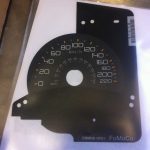 F150 Raptor KMH Speedo overlay
$115.00
F150 Raptor KMH Speedo overlay
$115.00
-
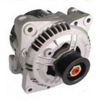 MAZDA ROTARY BOSCH ALTERNATOR HIGH OUTPUT 110 AMP
Original price was: $455.00.$400.00Current price is: $400.00.
MAZDA ROTARY BOSCH ALTERNATOR HIGH OUTPUT 110 AMP
Original price was: $455.00.$400.00Current price is: $400.00.